The PCW series uses the Zilog Mostek Z80 processor, a processor that can handle only 64 kilobytes. All standard programs use no more than that. A standard PCW has either 256 or 512 kilobytes (the new PCW 16 has 1024 kb but is not compatible with other PCW's in this respect). The unused memory is assigned to a RAM disc, a volatile disc that is fast compared to a disc drive. It is used for copying disc too. Upgrading memory will allow you to store more documents in drive M: and to copy a single sided A drive disc in one go (the source disc does not have to be inserted a second time). A lot of programs are specially written for the PCW and require at least these 512 kilobytes (e.g. LocoScript 3). Some of these programs will benefit from even more (Disckit, LocoScript 3, MicroDesign III, Flipper, The Network etc.), but upgrading above 512 kb can only be achieved by means of an add-on.
The PCW 8256 and PcW 9256 (see the specific page on the 9256) can be upgraded from 256 kilobytes to 512 kilobytes on board. The PCW 8512, PCW 9512, PcW 9512 and PCW 10 already have 512 kilobytes. Adding more memory than 512 kb is also possible, by means of an add-on. More about that in future... This article covers on board upgrading only. The new PCW 16 (released in 1996) has one megabyte and upgrading is done in a different way. The integrated circuits needed for the upgrading of the 8256 and 9256 are of a standard type: the NEC 41256, suitable types range from 100 - 150 nanoseconds (Amstrad prescribes 150, but the faster 100 ns are cheaper and more readily available). Eight of those chips are required and at present these will set you back about NLG 30. Second hand chips, readily available for budget prices, can be used too, when marked something ranging from 41256-10 to 41256-15 (the last two digits indicate the speed: 100 and 150 nanoseconds).
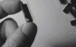
First something about IC's, integrated circuits, or chips as they are usually called. Chips are very vulnerable: static electricity should be avoided, as well as touching them in the wrong places. The picture shows the way to pick them up. It also shows two severely bend pins - this is no problem. They can be aligned using a ruler or simply the tableside... As long as you avoid the static electricity chips are no objects to be afraid of: it is not necessary to handle them with extreme care. If you fail to insert them properly in the sockets and bend one in the process, no big deal: just realign them. Just be careful not to touch or break any of the pins: that would be fatal, though not very expensive. Basically the only thing to watch carefully is the 'notch' on the IC which shows the proper way to insert it in the socket. You can see from the original 8 chips in what direction the notch should point.
In order to upgrade the memory the back of the PCW should be removed. Place the machine screen down on a towel or something like that and remove the motherboard. The disc drive connectors must be disconnected as well as the blue, the black and the grey connectors. The grey one is a tough one, usually requiring a lift with a flat-bedded screwdriver. Having disconnected all cables the board can be lifted out of the PCW.
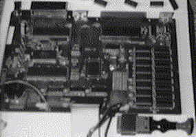
Put the board on a flat surface (avoid static electricity and touch it only in places where no contacts are present) and take some time to study it. Note the 16 sockets for memory chips on the right side of the picture: 41256 chips already occupy at least 8 of them.
The pair of pliers below is a special tool used for handling integrated circuits. Such a device, however, is not necessary to insert chips, just comes in handy when you should need to remove a chip again. You can identify the way chips should be inserted in the sockets by means of the text on the chips or from the location of the notch on the left side of the chips and the sockets (check the original chips).
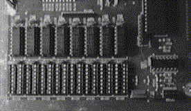
Close up of the memory banks, showing the eight empty sockets on the bottom. It does not matter from which side you start, but avoid an empty socket between two filled ones: it makes the operation harder. I always start working on the left side (of the picture) so that I avoid touching the board itself but this way you do have to avoid touching the IC's you inserted earlier. When you start working you rotate the board 90 degrees. Inserting the chips with the board turned as shown is asking for bend pins... This is not always a problem, but breaking them is always a potential risk and that would end the story for that chip.
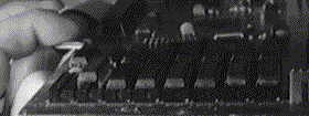
Close up of six occupied sockets, one empty and one chip halfway inserted (from right to left). The trick to successfully click a chip into place is to hold it on the sides with your thumb and index finger and then bring it down in such an angle that only the bottom pins touch the socket. Then apply pressure to the bottom and tilt the chip to horizontal position. When performed in a fluent motion the chip falls into place. Unfortunately you are most likely to really get the hang of it with the eight chip... Practice gains experience here...
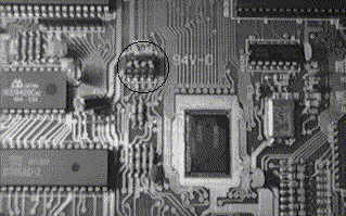
The last task is to set the dipswitches to the settings that are required for a 512 kilobytes PCW. Switch SW101 (a very small block of 4 switches) should be set: switches A and C off, switches B and D on. The text printed on the board states which position is up. Use a pencil to set it to the new settings. The circle in the picture shows the location of this switch. NOTE: some very early PCW's do not have a dipswitch but soldered connections. The settings remain the same, the operation changes: please contact the JCC if you have such an early model PCW. Some welding is required for these machines. Do note that a separate page is available for the PcW 9256 that has a jumper, rather than dip switches.
After assembling the PCW reports the increased memory size. You can test it by means of special testing software, a file copy program with a verify option (not being DISCKIT). Alternatively you can fill drive M: to capacity with LocoScript documents and check the contents: if no errors occur you may assume that there are none....
Owners of a PcW 9256 should read the next page on the specific details of their machine.